

- Rotation speed monitors for braking and conveyor speed control
- Conveyor belt speed monitors and material flow control switches
- Rope and push button operated emergency STOP switches
- Pull rope emergency switches according to DIN/VDE 0660 T200/T210, EN 218
- Off track belt switches according to VDE
- Pull rope and emergency switches with Ex protected contacts according to ATEX guideline for use in zone 21 and 1
- Unlocking devices for supervisory control of drives
- Infrared sensors for steel factories, smelting works and rolling mills
- High temperature proximity sensors
MEYLE Safety switches and gear limit switches

Meyle safety switches and gear limit switches
Flyer safety equipment for conveyor belts and machine protection
Safety switches
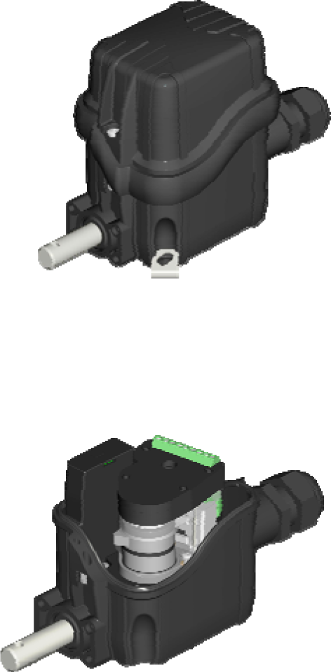
Type Al-Ni 6 – Rotation Speed Monitor

General
The Al-Ni 6 is for attachment to the shaft end of large machines or motors to monitor their running up, reaching the nominal speed and stopping at braking. Monitoring of conveyor belts is possible by rolling wheels. The Al-Ni 6 is the successor of the proven Al-Ni 5. It’s dimensions at clutch flange and size have been maintained from it’s predecessor and the function principle is compatible. With respect to the lower switching power the Al-Ni 6 is appropriate for monitoring slow-down, revolution and conveyor belts. As an advantage the Al-Ni 6 features a digital adjustment of the switching speed (r.p.m.) by code switches. The adjustment range is from 60 r.p.m. up to 6000 r.p.m. (1-100 revolutions per second) in steps of 60 r.p.m. and can be set independently for left and right turning.
Function Principle
When the shaft is turned a stepper motor induces the supply power for the signal processing circuits and the signal voltages for determination of revolution and direction. When the speed selected by the code switches is reached relay 1 switches at left turning and relay 2 switches at right turning.
Rotation speed motor Al-Ni 6 – datasheet
Type BWA – Conveyor belt speed monitor

Application
Our conveyor belt speed control switch BWA is an electromechanical device for electrical monitoring of the speed of any conveyor belt, including the scheduled running-up of belts.
In operation, a roller is pressed against the lower side of the conveyor belt. As the belt transverses, a magnetic field is generated and is dependent on the speed and direction of travel of the conveyor belt. This action results in activating the switching contacts via the inner adjustable spring and lever mechanism. Per rotation direction a single circuit two-way contact is actuated and is adjustable for a given speed range.
Each of these contacts can be individually used to monitor the running-up or running-down speed. The switch bearing is an antifriction bearing allowing for maintenancefree operation. The metal housing of the switch is of type IP 55 (conforming to the German standard).
The following executions are available in order to cater for different requirements: Switch type BWA has its roller in direct contact to the fixing foot. This version is designed to be installed with the roller in contact with the lower belt adjacent to a support roller. The displacement force is determined by the installation position.
Switch types BWA 500 and BWA 750 are equipped with a movable spring-loaded lever with lengths of 500mm or 700mm. The switch roller is designed to be positioned against the underside of the upper belt with the springloaded lever tension. Reliable switch operation is guaranteed even if the belt height deviates by ±30mm.
Different roller diameters are available for the above switches to conform to different line speed ranges.
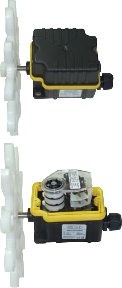
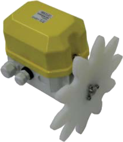
Type MFG M/J – Material flow control switch

Application
Material flow control switches are provided to be safely installed for the automatical operation of conveying plants. They control the charge height of the conveying belt as well as the interruption of the material flow. MEYLE material flow control switches MFG are equipped with a dragging sheet leaded over the belt by a joint pipe measuring around 50 cm long. This dragging sheet lies on the conveying belt or on the bulk material due its dead weight. During the transport of bulk material on the belt, the dragging sheet is highly different displaced. After having achieved the displacement height being internally adjusted, the change-over effects. For a reliable, maintenance-free operation, all shafts are ball beared. The solid steel housing with the type of enclosure IP65 enables a high operating field. The dragging sheet is fastened with only one nut and, consequently, easy to be exchanged. It is mountable either for left or right direction of belt motion. Should the dragging sheet be too heavy for your special operation, a version with an adjustable counter weight is available. According to your specification, the material flow control switch is equipped either with a proximity switch or with a micro switch. Both should be in accordance with the following selection table. The micro switches have the advantage to a direct high switching capacity and the proximity switches are distinguished by free wear and a practically free hysteresis step back.
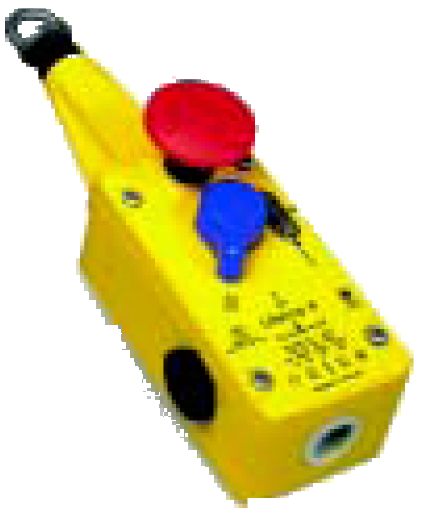
Type Lifeline 4 – Rope and Push button actuated Emergency STOP Switch
Description
The Lifeline 4 cable/push button operated system can be installed along or around awkward machinery such as conveyors and provide a constant emergency stop access. The Lifeline 4 is the only device of its kind to incorporate the following features in one unit making it the most versatile cable switch on the market. 1. The positive mode mechanism ensures that the contacts are immediately latched open on actuation and can only be reset by the intentional action of turning the blue reset knob. The design also protects against nuisance tripping and the effects of thermal expansion. 2. A mushroom head emergency stop button is included on the unit to provide E-Stop access even at the extreme ends of the span. 3. The cable status indicator makes the system easy to set up and maintain for spans up to 125 meters. 4. Four sets of contacts are provided: 2 N.C. + 2 N.O., 3 N.C. + 1 N.O., or 4 N.C. contacts. 5. Sealed to IP 66 with rugged construction using die cast alloy and stainless steel to withstand harsh conditions.
Features
- Switches up to 125 meter span
- Universal mounting and operation
- Lid mounted emergency stop button, designed to conform to EN418
- Switch lockout on cable pulled and cable slack
- Cable status indicator on switch lid
Type NSR VDE approved – Pull Rope Emergency Switch

Application
According to DIN / VDE 0660 T200 / T210, EN 418, and the general stipulations of the incident prevention order VB610, devices or entire industrial machines and installations must be able to be switched off as quickly as possible by activating an emergency switch-off device in the case of possible danger to persons or damages to machines and installations. The pull rope emergency switches types NSR (with fork lever) are meeting the standards of DIN / VDE 0660 T200 / T210 and EN418. These switches must be used in control current circuits only. They serve as devices to prevent incidents, injuries and damages to production assets as e.g. conveyor belts in the iron & steel industry, mineral exploitation industry, loading & unloading facilities, chemical industry and mining. The pull rope emergency switch type NSR including accessories is for installation on the accessible side of conveyor belts or machines. It can be activated at any point of the line surveyed (an advantage over push-button type emergency switch-off is distributed in distances over the line to be monitored) and, depending on the switching logic, deactivate one or more drives or an entire complex, too.
Configuration and Features
The rope switch consists of a weather proof glass fibre reinforced plastic housing (yellow RAL 1004) with enclosure IP65. It is equipped with two holes for leads PG 16 which are plugged for shipping (do not use in operation). The switching mechanism makes the pull rope emergency switch staying operational even in case of broken springs. Its fail safe features correspond to the EN418 and the recommendations of the trade association: The pull rope emergency switch locks automatically and self driven after activation and can be reset only by the reset lever at the switch. If required, the reset lever can be made lockable as well. The item is available with 1, 2, or 3 switching elements cogently operated by the switching mechanism. Additionally, a signal lamp can be accommodated in the cover. With the pull rope mounted on both sides of the activation lever a line length of about 100 m (max. 150 m) can be monitored. The switch will be activated automatically by pre-loading via pull springs in case of a rope rupture on one side.
Emergency switch Type NSR – datasheet
Type Switch SN VDE-aproved – Pull-rope Emergency

- Double-sided actuation for up to 50 m rope each · Up to 4 contacts NO and 4 contacts NC
- Interlocking in actuated position with manual reset only
- Snap action safety contacts with forcedopening system
- Meet any new European Security Standard
- Certified according to VDE-0660/200
- Reliable operation by high rope tension and large actuation travel
- 2 cable inlets with PG 16 or ½“NPTF threads
- Type of enclosure IP 65
- Version with CSA (Canadian Standard Association) approval.
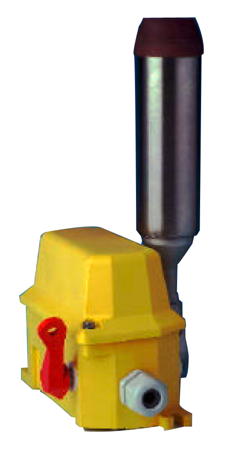
Type SK with pull-rope emergency switch, horn and warning light – Signal Combination
Uses
Present day trade unitons and trade associations demand stricter measures for prevention of accidents on which technical supervisory bodies base their regulations also.
One of these safety measures is the installations of emergency pull-rope switches, which have proven their value in the prevention of damage in numerous conveyor belt systems, in mealurgical plants, in the mineral industries, in transspipment installations, in the chemical industry and open cast mining.
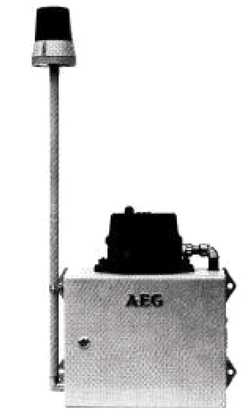
Type SM with pull-rope emergency switch, horn and flashing light – Alarm signal post
Application
The trade co-operative associations of today demand sharper measures for prevention of accidents, which are also used as guidelines by the technical supervisory bodies.
One such safety measures is the installation of pull-rope emergency switches. They have proved themselves an effective means of accident prevention on innumerable conveyor belt systems, in iron and steel works, in the quarrying and earth moving industries, in trans-shipment facilities, the chemical industry and open pit mining.
For extended conveyor systems In particular, such pull-rope emergency switches can be supplied as alarm signal post type SM. This alarm signal post is installed on the approach side of conveyor belt systems or machines and - apposed to the Emergency-OFF push buttons located at certain intervals - it can be operated at any point along the length of a section and, depending on the system, can disconnect single or multiple drives or even the total plant as a whole. The actuated switch is identifiable by way of the visual and audible signals.
Design
The alarm signal post type SM consist of
pull-rope emergency switch
- flashing light
- horn
- terminal box
Type BSR and Type BSO VDE-approved – Off-Track Belt Switches
Application
The straight run of troughed conveyor belts is a decisive factor in safe, economic operation. In spite of several mechanical precautions, external influences caused by local conditions may effect the belt's straight running.
The most frequent causes for slant running are
- soiling of the support rollers and tail belt drums
- off-center material loading
If such or similar situations occur, the conveyor belt concerned and the supply belts are to be switched off to prevent damage, destruction, spillage of material, erroneous discharge, and the resulting expensive consequences.
BSR belt switches – datasheet
Typ FSR und FSO VDE-tested – Off-Track Belt Switches

Application
The straight run of troughed conveyor belts is a decisive factor in safe, economic operation. In spite of several mechanical precautions, external influences caused by local conditions, may effect the belts straight running.
The most frequent causes are
- soiling of the support rollers and tail belt drums
- off-center material loading.
If such or similar situations occur, the conveyor belt concernd and the supply belts are to be switched off to prevent
- damage
- destruction
- spillage of material
- erroneous discharge
and the result possibly expensive consequences
Design
Operation mechanism and switching elements of the switches FSO and FSR are accomodated in a sturdy, glass-fiber reinforced plastic housing, enclosure IP 65, Which meets in every aspect heavy duty requirements. Two threaded bushes for cable glands PG16 are provided for lead-in. The switching mechanism is designed in such a way that the track-off belt switch remains operational even with a damaged retraction spring. In order to prevent loss of functional safety as a result of soiling, the retraction spring has been placed inside the housing.
The off-track belt switch FSO is provided with a switch mechanism without latch, the type FSR with an effective latch when being operated.
The release cam lever only latches when the switching position is reached. With constant movement of the roller.
Lever by the belt, mechanical wear and tear is thus avoided. Unlatching can take place locally by an incorporated or separately supplied release lever.
The off-track belt switches of the types FSO and FSR are available with two or three switching elements respectively. In the case of the the switches FSO 2/1+V, two switching elements for the limit switching-off with a lever deflection of 12°-15° are provided for.
The robust, long roller lever is equipped with ball bearings and suitable for deflection of 75° on both sides. The devices nearly do not need any maintenance.
Type FSR-EML und FSO-EML – Off-Track Belt Switches with EX-protected contacts

Application
The straight run of troughed conveyor belts is a decisive factor in safe, economic operation. In spite of several mechanical precautions, external influences caused by local conditions, may effect the belts straight running.
The most frequent causes are
- soiling of the support rollers and tail belt drums
- off-center material loading.
If such or similar situations occur, the conveyor belt concernd and the supply belts are to be switched off to prevent
- damage
- destruction
- spillage of material
- erroneous discharge
and the result possibly expensive consequences.
Design
The equipment of these switches with EX-protected and approved contacts qualifies them for use in explosive areas zone 21 as well as zone 1 according to the ATEX-guideline. The design of these misalignment switches considerates heavy duty service. Housings made of grey cast iron or of most stable, impact resistant, thickwalled and strongly oxydating atmospheres resistant fibre glass reinforced polyester as well as the roller levers made of stainless steel, are the best guarantees for long years of reliable service. Both housings are IP66 protected (water- and dust proof). These misalignment switches should be installed pairwise, left and right of the conveyor. In case that the conveying belt misalign from the given track, one roller lever of these switch pair will be touched by the edge of the belt and displaced against the resetting force of an switch-internal spin. Actuation of the contacts is being effected in snap-action characteristic if the lever is displaced 7cm out of the neutral position. The maximumdisplacement angle of the roller lever is 75°. Optional is a 2- stage switch, first stage for signalling and the second stage for cut off. Signalling happens at a displacement of 4 cm, cut off at 7 cm. In case that the value of misalignment is reduced reset happens automatically. A further version provides latching in main contacts actuated position. Stepless adjustable space between the roller lever and the edge of the belt by stepless adjusting of the lever on the switch shaft facilitates installation. The contact surfaces are made of silver or are gold plated optional. For low tensions and smallest currents the gold contacts are recommended. 1 or 2 cables, standard 5 m long each, fix welded to the contacts, are for electrical connection either in EX-free or EX-protected atmospheres.
Type HE-...-Z – Lever Limit Switch

- Up to 4 contacts NC and 4 contacts NO
- Snap action safety contacts with
- forced-opening system
- 2 cable ducts Pg16
- Available with impact resistant
- glass fibre reinforced polyester,
- optional cast iron enclosure
- Type of enclosure IP 65
- EEX protected version available
- Version with CSA (Canadian Standard Association) approval
- Automatic latching in actuated position with manual reset
Lever Limit Switches are designed for signalling or cutting off at reached positions of linear or sviveling movements.
MEYLE Lever Limit Switches of these types are equipped with an actuation lever which is pressed through an internal spring in its neutral position. When the roller of this actuation lever is moved against a cam or an actuation bar, the actuation lever is displaced from its neutral position to one of the both possible sides (left or right) against the force of the internal spring. At an displacement angle of 30° the commutation will happen in snapaction characteristic with a forced opening of the NC-contacts. When leaving the area of cam or actuation bar, the lever is turned back to its neutral position through the force of the internal spring and resetting happens with snap action (except for version „R“. At this point the actuation lever will be latched in actuated position automatically. Release of this latching only manually direct at the switch).
These switches can be equipped with up to 4 switching elements. Each switching element consists of one contact NC and one contact NO. They are actuated either simultaneously independent on the direction of displacement of the lever or they are actuated depending on the direction (see „selection table). Commutation is being effected at a displacement angle of 30°. The maximum displacement angle of roller lever is 75°.
The lever can be mounted in 4 positions on the shaft. The roller of the actuation lever is made of polyamide and is sleeve -beared on a stainless steel axle.
The housing of this switch is made either of coloured, glass fibre reinforced polyester or of cast iron (code „M“). Stability of the polyester enclosure is comparable to that of cast iron enclosures. Polyester, however, is not so brittle and thus more resistant against shocks. Both are dust- and waterproof housings (conforming to IP65).
The switches are guaranteed for an extended working life: The use of sealing rings protecting all ducts out of the housing, shafts made of stainless VA-steel, screws made of stainless VA-steel, lossprotected lid screws.
Variations
- Pull-off release lever
- CSA-aproval (separate data sheet)
- EEX and SCH protected version (separate data sheet)
- For easier installation of the electrical wiring a 8-digit clamp with internal wiring can be provided
- Pre-contacts for prewarning at displacement angle of roller lever of 15°
Type SNHDL/R – Pull-rope Emergency Switch for Heavy Duty

Protection up to 125 meters
The SNHDL/R is a robust die-cast Heavy Duty Safety Rope Pull switch designed to protect long conveyor lengths were protection is required up to 125m. using two switches or up to 100m. using a single switch.
The die-cast housings are robust to survive indoor or outdoor use. A bi-colour LED ensures switch status can be seen easily from a distance. They have 4NC 2NO contacts to ensure flexibility with all modern control applications and optional Explosion Proof contact blocks are available. They can be used to compliment the SNHD versions at each end of the rope span.
Type SNHDL/R – Pull-rope Emergency Switch for Heavy Duty catalog
Type SNM – Pull-rope Emergency Switches for Mini Duty

Protection up to 50 meters
The SNM a compact yet robust die-cast Mini Duty Safety Rope.
Pull switch designed to protect short conveyor lengths were protection is required up to 50m using two switches or up to 30 m using a single switch.
They provide reliable, cost effective safety solutions for conveyor systems and can be enhanced by adding external mushroom type E Stop at the switch or bi-colour LED available to show switch status from a distance.
They have a choice of 3 or 4 pole contacts to ensure flexibility with all modern control applications. Rugged integral sealing bellows means they can be high pressure hosed
Type SNM Pull-rope emergency switches catalog
Type SNS – Pull-rope Emergency Switch for Standard Duty

Protection up to 50 meters
The SNM a compact yet robust die-cast Mini Duty Safety Rope.
Pull switch designed to protect short conveyor lengths were protection is required up to 50m using two switches or up to 30 m using a single switch.
They provide reliable, cost effective safety solutions for conveyor systems and can be enhanced by adding external mushroom type E Stop at the switch or bi-colour LED available to show switch status from a distance.
They have a choice of 3 or 4 pole contacts to ensure flexibility with all modern control applications. Rugged integral sealing bellows means they can be high pressure hosed
Type SNS Pull-rope emergency switches for standard duty catalog
Type SNS-SS Stainless Steel – Pull-rope Emergency Switch for Standard Duty

Protection up to 100 meters
The SNS-SS is a General Duty Safety Rope Pull switch designed to protect long conveyor lengths up to 100 m. The Stainless Steel 316 housings are designed specifically to withstand the tough environments found in the Food and Pharmaceutical industries. The fixing holes are under the cover of the switch to prevent food trap areas. They are all purpose switches and will survive chemical and detergent washdown by providing all stainless steel parts and robust IP67 sealing by using integral bellows and gaskets.
An easily seen bi-colour LED is available to show switch status from a distance and they have a choice of 3 pole, 4 pole or Explosion Proof contact blocks to ensure flexibility with all modern control applications.
Shorter rope spans up to 80m. can be achieved by using just one switch therefore making a cost effective solution and also reducing electrical wiring runs.
Type SNS-SS Stainless Steel – Pull-rope Emergency Switch for Standard Duty catalog
Type SNHD – Pull-rope Emergency Switch for Heavy Duty

Protection up to 250 meters
The SNHD is a Heavy Duty Safety Rope Pull switch designed to protect long conveyor lengths. The die-cast housings are robust to survive indoor or outdoor use including washdown (IP67 rating).
Lengths over 2 Km can be achieved with less than 20 switches.
A bi-colour LED ensures switch status can be seen easily from a distance. They have 4NC 2NO contacts to ensure flexibility with all modern control applications and optional Explosion Proof contact blocks are available.
Shorter rope spans up to 200m. can be achieved by using just one switch therefore making a cost effective solution and also reducing electrical wiring runs.
Also availible as SNHD-SS Stainless Steel 316 housing for IP 69K
Type SNHD – Pull-rope Emergency Switch for Heavy Duty catalog
Rotary gear limit switch for motion and position detection
CRLS – Gear Limit Switch with Encoder

- Simple adjustable cams
- Mounting of incremental or absolute encoder
- Integrable into Pitch Control
- Cold climate version up to -40 °C
- Protection IP 65
Description
Robust geared limit switch with encoder. Precise adjustable cam.
Gear Limit Switch CRLS – datasheet
ERLS – Rotary gear limit switchesw yaw/pitch

- Simple adjustable cams
- Free from backlash, special pinion gear
- Protection IP 60
- Incremental or absolute encoder
- Flexible gear ration
- Cable or connector interface
Description
Robust gear limit switch with encoder. Precise adjustable cam.
ERLS – Rotary gear limit switches – datasheet
ARSLA – Rotary gear limit switch

- Ratio range 1:1 to 1:850
- Single ended shaft (Option: Double ended shaft)
- Precise adjustment of each CAM
- Heavy duty design
- Available with 1 contact assy (4 contacts max.) or 2 contact assys (8 contacs max.)
- Potentiometer or incremental/absolute encoder mounting possible
- IP 67
- 1 NO, 1NC contact/CAM (standard)
The ARLSA series rotary limit switch is used to control the movement of industrial machinery. It operates as an auxiliary controller of electrical motors through a power interface, such as a contactor or PLC. Its shaft can be connected to the motor and, after a set number of revolutions, the cams operate the switches, thus starting the predetermined movement. Typical applications are lifting, travelling and slewing gears of cranes, yaw and pitch control in wind power stations, bucket elevators, etc.
ARSLA – Rotary gear limit switch datasheet
ARSLB – Rotary gear limit switch
- Ratio range 1:16 to 1:800
- Single ended shaft
- Precise adjustment of each CAM
- Heavy duty design
- Available with 1 contact assy (4 contacts max.)
- IP 67
- 1 NO, 1NC contact/CAM (standard)
The ARLSB series rotary limit switch is used to control the movement of industrial machinery. It operates as an auxiliary controller of electrical motors through a power interface, such as a contactor or PLC. Its shaft can be connected to the motor and, after a set number of revolutions, the cams operate the switches, thus starting the predetermined movement.
Typical applications are lifting, travelling and slewing gears of cranes, yaw and pitch control in wind power stations, bucket elevators, etc.
ARSLB – Rotary gear limit switch – datasheet
ARLSC – Rotary gear limit switch
- Ratio range 1:15 to 1:150
- Single ended shaft
- Precise adjustment of each CAM
- Heavy duty design
- Available with 1 contact assy (4 contacts max.)
- IP 67
- NO, 1NC contact/CAM
The ARLSC series rotary limit switch is used to control the movement of industrial machinery. It operates as an auxiliary controller of electrical motors through a power interface, such as a contactor or PLC. Its shaft can be connected to the motor and, after a set number of revolutions, the cams operate the switches, thus starting the predetermined movement.
Typical applications are lifting, travelling and slewing gears of cranes, yaw and pitch control in wind power stations, bucket elevators, etc.
ARLSC – Rotary gear limit switch datasheet
BRLS – Gear cam limit switches

- Combined worm/spur gears for high gear reductions requiring less mounting space; different, precisely graduated gear reduction
- Cam discs with precise adjustment
- Utilisation of switching contacts for switching voltages of 250 VAC, gold contacts on request
- Available with 4 contacts in 1 contact assembly block or 8 contacts in 2 contact assembly blocks
- Heavy duty ball bearing design
- Plastic housing IP 65
- 0,85 to 880 usable revolutions
- Potentiometer and up to 2 incremental or absolute encoder mounting possible
BRLS series geared cam limit switches are universal mechanical switching devices which present a large number of input shaft revolutions on the rotation angle of one single revolution of the cam discs. The cam discs serve to operate the contacts. BRLS series geared cam limit switches are used wherever specific ranges of travel can be limited indirectly only by switching devices. Classical applications of these limit switches are lifting, travelling and slewing gears of cranes, yaw and pitch control in wind power stations, bucket elevators, etc. Especially where a danger to persons exists and the use of positive opening switching contacts is required according to EN 60947, part 5 − 1, IEC 947 − 5 − 1, the use of geared cam limit switches is the most efficient alternative.
Construction of the geared cam limit switch
The geared limit switch consists of a gearbox and switch combination which are located within a housing. The torque is positively transmitted from the input shaft to the switching shaft and, when using the precise adjustment "FV" of the cam discs, it is also transmitted up to the contact. The gear housing is made of glass − fiber reinforced synthetic material, the cap is not reinforced. Mounting as required.
Protection IP 65 to DIN VDE 0470 − 1 / EN 60529.
Working temperature -40 °C to +80 °C.
At 3 sides the housing is provided with pre − cut holes for cable entries which can be opened by the customer if necessary.
For fixing of the cable entries, insert fixing nuts. These nuts are protected against torsion. The thread lengths of the required glands are stated on the dimensional drawing.
The housing is provided with formed feet. If required, an additional flange can be screwed to the shaft input.
BRLS – Gear cam limit switches
HRSLA – Rotary gear limit switch

- Precise adjustment of each CAM
- Single or double ended shaft
- Microswitches with gold contacts
- Up to 4 CAMs in one contact block
- Heavy duty design
- Plastic housing IP 65
- Ratio range 1:1 to 1:450
- Potentiometer and incremental or absolute encoder mounting possible
Rotary gear limit switches are used for yaw control (azimuth control) and pitch control. For yaw control they monitor the position of the nacelle and avoid twisted cables (cable twist sensor). Additional accurate positioning can be achieved by integrating a MEYLE incremental or absolute encoder or a potentiometer.
In pitch control applications the rotary gear limit switch monitors the position of the rotor. This is usually achieved through the integration of a MEYLE high resolution encoder.
The rotary gear limit switches are connected with the gear box of the nacelle or of the rotor by a pinion. These pinions can be made according to customers specification in size and number of teeth.
The rotary gear limit switches are designed for use in rough conditions and cold climate up to -40 °C.
HRSLA – Rotary gear limit switch datasheet
FRLS – Worm spur geared limit switch

- Worm spur gears
- Comply with Quality management
- Robust housing
- Protection IP 67, EN 60529, NEMA 6
- Free programmable Cams
- Revolutions 1:1 to 8000:1
- Microswitch silver or gold 6A, 250VAC
- Switching with forced separation, EN60947
- Switches with roller
- Terminal rail for easy mounting
- All gears are lifetime lubricated
- Shaft made of stainless steel
- Ambient temperature -40 °C to +95 °C
- Optional with position sensors available
- From switch to shaft positively driven
- High precise adjustment Cam
Description
Robust worm spur geared limit switch with optional position sensors like incremental encoder or absolute encoder or 4-20mA. Precise adjustable cam and controlled opening micro switches.
For use in Heavy duty industries and safe applications like Wind power, Rail industry, Mining industry, Material handling, Packaging equipment, Processing equipment , Conveyor belt , Cranes, Offshore plants, Commercial solar plants etc. which require a precise feedback signal to operate in very harsh environments.
FRLS – Worm spur geared limit switch datasheet
BRLS-LV – Geared cam limit switches
- Combined worm/spur gears for high gear reductions requiring less mounting space; different, precisely graduated gear reduction
- Cam discs with precise adjustment
- Utilisation of switching contacts for switching voltages of 36 VDC, gold contacts on request
- Available with 4 contacts in 1 contact assembly block or 8 contacts in 2 contact assembly blocks
- Heavy duty ball bearing design
- Plastic housing IP 65
- 0,85 to 880 usable revolutions
- Potentiometer and up to 2 incremental or absolute encoder mounting possible
BRLS series geared cam limit switches are universal mechanical switching devices which present a large number of input shaft revolutions on the rotation angle of one single revolution of the cam discs.
The cam discs serve to operate the contacts.
BRLS series geared cam limit switches are used wherever specific ranges of travel can be limited indirectly only by switching devices.
Classical applications of these limit switches are lifting, travelling and slewing gears of cranes, yaw and pitch control in wind power stations, bucket elevators, etc. Especially where a danger to persons exists and the use of positive opening switching contacts is required according to EN 60947, part 5 − 1, IEC 947 − 5 − 1, the use of geared cam limit switches is the most efficient alternative.
Construction of the geared cam limit switch
The geared limit switch consists of a gearbox and switch combination which are located within a housing. The torque is positively transmitted from the input shaft to the switching shaft and, when using the precise adjustment "FV" of the cam discs, it is also transmitted up to the contact. The gear housing is made of glass − fiber reinforced synthetic material, the cap is not reinforced. Mounting as required.
Protection IP 65 to DIN VDE 0470 − 1 / EN 60529.
Working temperature -40 °C to +80 °C.
At 3 sides the housing is provided with pre − cut holes for cable entries which can be opened by the customer if necessary.
For fixing of the cable entries, insert fixing nuts. These nuts are protected against torsion. The thread lengths of the required glands are stated on the dimensional drawing.
The housing is provided with formed feet. If required, an additional flange can be screwed to the shaft input.
BRLS-LV – geared cam limit switches
RLS2C – Rotary gear limit switches

The rotary limit switch is used to control the movement of industrial machinery. It operates as an auxiliary controller of electrical motors through a power interface, such as a contactor or PLC. Suitable for heavy duty, its shaft is connected to the motor and, after a set number of revolutions, the cams operate the switches, thus starting the predetermined movement. A worm gear and a helical toothed gear combined with one or more pairs of straight toothed gears are used for the transmission of the movement from the input shaft to the output shaft.
RLS2C – Rotary gear limit switches
RLS4C – Rotary limit switch

The rotary limit switch is used to control the movement of industrial machinery. It operates as an auxiliary controller of electrical motors through a power interface, such as a contactor or PLC. Suitable for heavy duty, its shaft is connected to the motor and, after a set number of revolutions, the cams operate the switches, thus starting the predetermined movement. A worm gear and a helical toothed gear combined with one or more pairs of straight toothed gears are used for the transmission of the movement from the input shaft to the output shaft.
Revolution ratios ranging from 1:1 to 1:295 result from the use of different combinations of gear wheels between the input shaft and the output shaft, which is connected to the cams operating the switches. Transmission and gear driving shafts are made of stainless steel to prevent oxidation and wear. The gear wheels and the driving bushes are made of self-lubricating thermoplastic material, suitably chosen to reduce the wear to a minimum and to maintain the accuracy of the couplings over time. Sintered bronze bushes are moulded into the base of the limit switch to optimise the shaft rotation and to prevent rubbing with plastic material.
Each cam can be set with great accuracy thanks to the cam adjusting screws. The auxiliary switches are of a positive opening type, thus suitable for safety functions. It is available with direct control switches for operating directly on the motor. The cam-switch sets can be substituted for potentiometers suitable for the connection to electronic equipment.
Materials and components are wear resistant and protect the equipment against water and dust. The limit switch is available with a flange for direct coupling to the motor and it can be customised with labels and colours according to the customer’s requirements.
RLS4C – Rotary limit switch Datasheet
Position Limit Switches
PLRZ-PLSC – Position Limit Switches

Position limit switches are designed to control the movement of overhead travelling cranes, hoists and machine tools. They operate as auxiliary controllers of electrical motors through power interfaces, such as contactors or PLCs.
Both the enclosure and the head of the limit switches are made of thermoplastic material (nylon reinforced with fi bre glass). Materials and components ensure high resistance and endurance and protect the equipment against water and dust.
The PLSC series has “T” or “Cross” rods which may move to 3 or 4 maintained positions, while the PLRZ series features a single rod or a rod with roller with spring return movements.
The limit switches are equipped with 1NO+1NC snap action switches or, upon request, with 1NC slow action switches. All switches are of the positive opening type, thus suitable for safety functions.
PLRZ-PLSC – Position Limit Switches datasheet
PLTA – Position Limit Switches

PLTA is a position limit switch designed to control overhead travelling cranes, hoists and machine tools. It operates as auxiliary controller of electrical motors through power interfaces, such as contactors or PLCs.
PLTA is the latest generation of position limit switches: the peculiar design and the use of high performing polymers ensure high resistance and endurance under the heaviest utilisation conditions. Its design and overall dimensions facilitate installation and maintenance operations.
Both the enclosure and the head of PLTA are made of thermoplastic material (nylon reinforced with fi breglass) ensuring wear resistance and protecting the equipment against water and dust. X-type rods can move to 4 maintained positions. Inner components are made of tecno-polymers guaranteeing a long life-cycle and constant performance even at extreme temperatures.
PLTA is equipped with 1NC slow action switches or, upon request, 1NO switches. All switches are of the positive opening type, thus suitable for safety functions.
PLTA – Position Limit Switches datasheet
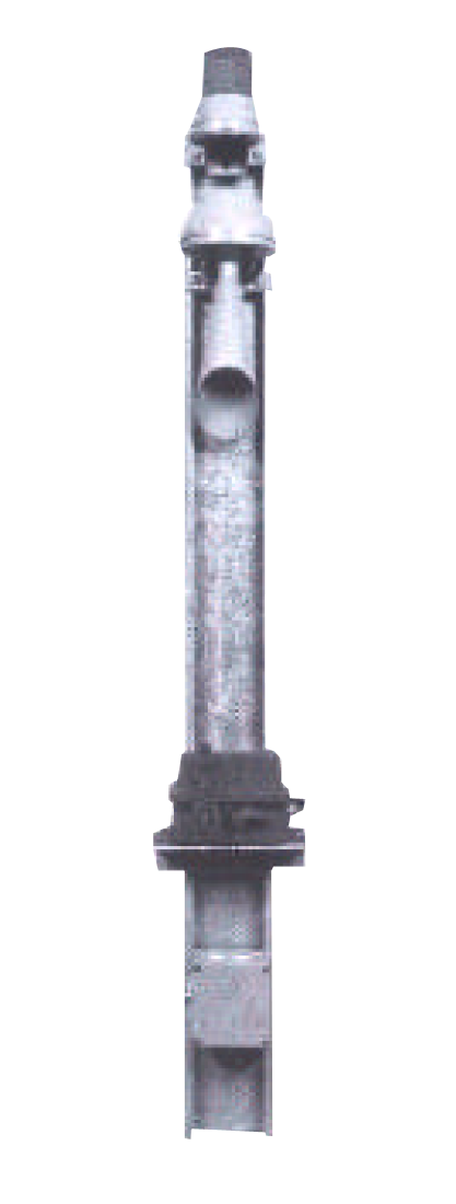
CGMYGES – Counterweight Limit Switch

The counterweight switch consists of a front housing part to bearing the drive (input) shaft and of a switch part, which are connected rigidly to each other. The weighted lever is mounted to the drive flange in such a way that the weight is situated to the bearing surface of the feet B3 by 20º to top . The weighted lever is designed to allow utilisation for counter-clockwise or clockwise operation provided that it is mounted accordingly to the drive flange. The also supplied steel rope connects the counter-weight and the weighted lever; it is fixed through the accordingly provided bore by 2 rope clamps each. At the counterweight a rope guide for the crane rope is provided. By lifting the counterweight, which is heavier than the weight, the switching shaft with the cam discs is turned. After taking-back of the lifting force at the counter-weight, it returns the switching shaft with the cam discs into the initial position. The final positions of the weighted lever are limited mechanically. When exceeding the upper switching point, the limit switch is not damaged mechanically, as long as the counterweight is not attracted towards the weighted lever. The cam discs fixed to the switching shaft, which are provided for actuation of the contacts, can be adjusted infinitely and independently from each other. In relation to the required contact arrangement, the cam discs can be fitted with 40° or 180° cams (standard ex− ecution) or with other degrees as special execution. Types of setting as per fig. 2 and 3. In relation to the protection, the housing is made of steel sheet (IP 54, IP 65) or gray cast (IP 56).
CGMYGES – Counterweight Limit Switch datasheet
Anti-collision sensors – Crane
CraneSonic

This microprocessor based device is designed specifically for distance measurement applications for fast marine port cranes as for example RTGC, OHBC and RMGC. The CraneSonic is designed to protect both directions.
The CraneSonic transmits electronic pulses to the ultrasonic transducer. The Transducer converts the electronic pulses to ultrasonic pulses which are emitted from the transducer face in a narrow beam. The CraneSonic measures the time from the pulse emission, to receiving the reflection (echo) from the next flat surface (crane bridge). Using the time measured, the CraneSonic calculates the distance from the transducer face to the flat surface.
The distance calculated is displayed on the Crystal Display (LCD). If the calculated distance is nearer than the programmed switch off parameter, the respective relays will set for slow down or stop.
Operator programming is accomplished using a infrared programmer and is stored in nonvolatile memory, unaffected by power interruption. The infrared interface permits one programmer to be used for any number of CranSonic. Upon programming completion, the removable programmer may be locked away, thereby securing all programming.
CraneSonic – datasheet
Crane anti collision device - Radar

Description
The radar barrier consists of two radar systems, which have contact with each other during operation. A break due to an obstacle between the two devices will be reported by an alarm output to both units. FMCW-Radar which works in the frequency range from 24,000 - 24,250 GHz is used. The antenna characteristics is 11° (± 5,5°) vertical and horizontal. This allows a high parralel offset. It will detect objects within a distance from 0,2 m up to adjustable 2 - 40 m.
Objects with a relative movement of a minimum speed from 5 cm/sec (3 m/min) will be detected.
Object detections will be reported by open-collector-outputs. The unit has 2 outputs which can be used for example as slow down or stop features. The output is by a 3-pin RSF4 standard connector. This device was especially developed for the anti-collison and start up protection in the field of fast moving marine port cranes, f.e. Straddle Carrier, RTGC, RMGC, STS and OHBC.
Advantages:
- high operating distance
- high parallel offset
- insensibility against environmental conditions
- high class of protection, heavy duty enclosure
- cost competetive solutions for new or existing cranes
Special brackets from the accessories program are helpful for easy mounting. For the re-fitting of existing equipment we offer an interfacebox with different input voltages and galvanically isolated outputs. Due to there physical properties, radar scanner devices must NOT be used for personal safety or EMERGENCY OFF functions.
Crane anti collision device - Radar – datasheet