

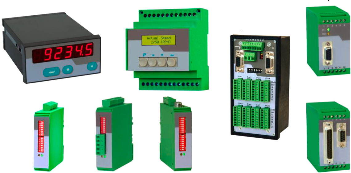
Signal converters with extremely short conversion times, high frequency range and easy signal adaptation. Digital displays with short response time, precision and flexible configuration of the operating mode.
MEYLE Displays and Converter
DEAX11564 – Display

Process Indicator with 2 Analogue Inputs, 2 Presets, Relay Outputs and Serial RS232 / RS485 Interface
- Two analogue inputs with independentscaling, each +/- 10 V or 0/4 – 20 mA
- Operating modes for display of input A or input B or the combinations [A + B], [A - B], [A x B] and [A : B]
- Useful supplementary functions like Tare function, programmable averaging functions, programmable linearization etc.
- Aux. output 24 V DC / 100 mA for sensor supply
Technical Specifications
Power supply DC: 24 V (17 - 30 V), approx. 100 mA (without aux. sensor supply)
DC current consumption (without sensors) : 18 V : 110 mA, 24 V : 90 mA, 30 V : 80 mA
Aux. output for sensors: 24 V DC, +/- 15%, 100 mA
Inputs: 2 analogue inputs (+/-10 V, 0 ... +20 mA, 4 ... +20 mA)
Input impedance: Current: Ri = 100 Ohms, Voltage: Ri = 30 kOhms
Resolution: 14 bits (13 bits + sign)
Accuracy: +/- 0.1%, +/- 1 digit
Relay outputs: 2 relays (dry change-over each), 250 VAC / 1 A / 250 VA or 100 VDC / 1 A / 100 W
Serial interface: RS 232 / RS 485, 600 (selectable) - 38 400 bauds
Ambient temperature: Operation: 0° - 45° ( 32 - 113°F), Storage: -25° - +70° (-13 - 158°F)
Housing: Norly UL94 - V-0
Display: 6 decades LED, high-efficiency orange, 15 mm (0.590")
Protection class: IP65 (front), IP20 (rear)
Screw terminals: Signal lines max. 1.5 mm² (.0023 sq in), Relays max. 2.5 mm² (.0039 sq in)
Minimum update time: 50 msec (display): 60 msec (switching outputs)
Weight: approx. 250 g (8.9 oz)
Conformity and standards: EMC 2004/108/EC: EN 61000-6-2, EN 61000-6-3; LV 2006/95/EC: EN 61010-1
DEAX11564 Display Datasheet
DEAX13567-70 – Display

Process Indicators with Two Analogue Inputs and Calculations
- Two analogue inputs with independentscaling, each +/- 10 V or 0/4 – 20 mA
- Operating modes for display of input A or input B or the combinations A + B, A - B, A x B and A : B
- Useful supplementary functions like Tare function, programmable averaging functions, programmable linearization etc.
- Powersupply 115/230 VAC and 17-30 VDC in the same unit
- Aux. output 24 V DC / 100 mA for sensor supply
DEAX13567: Process Indicator, Display only
DEAX13569: Process Indicator with 2 Presets and Optocoupler Outputs
DEAX13570: Process Indicator with Serial RS232 / RS485 Interface
Technical Specifications
Power supply AC: 115/230 V (+/- 12,5 %), 7,5 VA
Power supply DC: 24 V (17 - 30 V), approx. 100 mA (without aux. sensor supply)
Total AC power: 7,5 VA
DC current consumption (without sensors): 18 V : 110 mA, 24 V : 90 mA, 30 V : 80 mA
Aux. output for sensors: 24 V DC, +/- 15%, 100 mA (with AC and DC power input)
Inputs: 2 analogue inputs (+/-10 V, 0 ... +20 mA, 4 ... +20 mA)
Input impedance: Current: Ri = 100 Ohms, Voltage: Ri = 30 kOhms
Resolution: 14 bits (13 bits + sign)
Accuracy: +/- 0.1%, +/- 1 digit
Switching outputs (DEAX13569 only): 2 x PNP, max. 35 V, max. 150 mA
minimum response time 53 msec.
Serial interface (DEAX13570 only): RS 232 / RS 485, 600 - 38 400 bauds
Ambient temperature: Operation: 0° - 45° ( 32 - 113°F), Storage: -25° - +70° (-13 - 158°F)
Housing: Norly UL94 - V-0
Display: 6 decades LED, high-efficiency orange, 15 mm (0.590")
Protection class: IP65 (front), IP20 (rear)
Screw terminals: Signal lines max. 1.5 mm² (.0023 sq.in.), AC lines max. 2.5 mm² (.0039 sq.in.)
Minimum update time : 50 msec (display): 53 msec (switching outputs)
Conformity and standards : EMC 2004/108/EC: EN 61000-6-2, EN 61000-6-3; LV 2006/95/EC: EN 61010-1
DEAX13567-70 Display Datasheet
DEAX13568 – Display

Process Indicator with Two Analogue Inputs, Calculations and Programmable Analogue Output
- Two analogue inputs with independent scaling, each +/- 10V or 0/4 – 20 mA
- Operating modes for display of input A, input B as well as combinations [A + B], [A - B], [A x B] and [A : B]
- Fully programmable scaling and zero definitions
- Useful supplementary functions like Tare function, programmable averaging functions, programmable linearization etc.
- Powersupply 115/230 VAC and 17-30 VDC in the same unit
- Aux. output 24 VDC / 100 mA for sensor supply
Technical Specifications
Power supply AC: 115/230 V (+/- 12,5 %), 7,5 VA
Power supply DC: 24 V (17 - 30 V), approx. 100 mA (without aux. sensor supply)
Total AC power: 7,5 VA
DC current consumption (without sensors): 18 V : 110 mA, 24 V : 90 mA, 30 V : 80 mA
Aux. output for sensors: 24 V DC, +/- 15%, 100 mA (with AC and DC power input)
Inputs: 2 analogue inputs (+/-10 V, 0 ... 20 mA, 4 ... 20 mA)
Input impedance: Current: Ri = 100 Ohms, Voltage: Ri = 30 kOhms
Resolution: 14 bits (13 bits + sign)
Accuracy: +/- 0.1%, +/- 1 digit
Analogue outputs 0/4 - 20 mA (max. 270 ohms), 0 - +/-10 V (max. 2 mA)
Resolution 14 bits
Response times Display min. 50 msec.
Analogue outputs min. 58 msec.
Ambient temperature: Operation: 0° - 45° ( 32 - 113°F), Storage: -25° - +70° (-13 - 158°F)
Housing: Norly UL94 - V-0
Display: 6 decades LED, high-efficiency orange, 15 mm (0.590")
Protection class: IP65 (front), IP20 (rear)
Screw terminals: Signal lines max. 1.5 mm² (.0023 sq.in.)
AC lines max. 2.5 mm² (.0039 sq.in.)
Conformity and standards : EMC 2004/108/EC: EN 61000-6-2, EN 61000-6-3; LV2005/95/EC: EN 61010-1
DEAX13568 Display Datasheet
DEDX13567-70 – Display

Universal Display Units with Impulse Inputs
Operation modes:
- High Speed Position and Event Counter (100 kHz)
- Tachometer, Frequency Meter
- Baking Time and Processing Time Indicator (reciprocal speed)
- Timer, Stopwatch
- Speed Display from Transition Time between Start and Stop Impulse
- Additional Functions: Linearization, Brightness Control, Digital Filter etc.
DEDX 13567: Display only
DEDX 13568: Display with Analogue Output
DEDX 13569: Display with Two Presets and Switching Outputs
DEDX 13570: Display with Serial Interface
Technical Specifications
Supply voltage AC: 115/230 V (+/- 12.5 %)
Consumption: 7.5 VA
Supply voltage DC: 24V (17 - 30V)
Consumption (without sensor): 18 V = 120 mA, 24 V = 95 mA, 30 V = 80 mA (approx.)
Aux. voltage for encoder supply: 24V DC, +/- 15%, 120 mA (with AC + DC supply), (5 VDC / 120 mA with option TTLIN1)
AC Power: 7.5 VA
Inputs: 3 (PNP/NPN/Namur), A/B = Impulse, C = Reset
Input currents: 5.1 mA / 24 V (Ri = 4.7 kOhms)
Input level HTL (standard): Low: 0 ... 3,5 V, High: 9 ... 30V
Input level TTL (option TTLIN1): CMOS levels, Low: 0 ... 0.8 V, High: 3.6 ... 5.0 V
Max. input frequency: All counter modes: 100 kHz
All other operating modes: 25 kHz
Reset input C: 1 kHz (min. pulse duration 500 µsec)
Display update rate: approx. 7 msec (330 msec with tachometer operation)
Accuracy (frequency measurement): +/- 1 ppm +/- 1 Digit
Analogue output (DEDX13568): Current: 0/4...20 mA (load 0 - 270 ohms)
Voltage: 0...+/- 10 V (max. 2 mA)
Resolution analogue: 14 Bits + Sign
Accuracy analogue: 0.1%
Analogue response time: see 4.3.
Ambient temperature: Operation: 0° - 45°C ( 32 - 113°F)
Storage: -25° - +70°C (-13 - 158°F)
Housing: Norly UL94 - V-0
Display: 6 Digit, LED, high- efficiency orange, 15 mm (0.59")
Protection class: Front IP65, Rear IP20
Terminals: Signals max. 1.5 mm², AC power max. 2.5 mm²
Switching outputs (DEDX13569): PNP, max. 30 volts, max. 150 mA
Weight (net) approx.: 450 g
Conformity and Standards: EMC 2004/108/EC: EN 61000-6-2, EN 61000-6-3; LV 2006/95/EC: EN 61010-1
DEDX13567-70 Display Datasheet
DEIX11564 – Display

SSI Indicator with Two Relay Outputs and Serial Interface, for Use with Single-Turn or Multi-Turn SSI Encoders
- Clear LED display (15 mm / 0.59" size) with adjustable brightness
- Master- or Slave operation with clock rates up to 1 MHz
- Suitable for all SSI formats from 8 to 32 bits
- Two presets and relay outputs
- Serial RS232 / RS485 interface
- Numerous supplementary functions like Linearization, Bit Blanking etc.
Technical Specifications
Supply voltage DC: 24 V (17 - 30 V)
Consumption (without sensor): 17 V: 190 mA, 24 V: 150 mA, 30 V: 120 mA
Aux. output for encoder: 24 VDC, +/- 15%, 120 mA (with AC and DC supply)
Control Inputs: 3 inputs, A, B, C (PNP/NPN/Namur)
Input currents: 5.1 mA / 24 V (Ri = 4,7 kOhm)
Input level HTL: Low: 0 ... 2 V, High: 9 ... 35 V
SSI input frequency range: 100 Hz - 1 MHz
Min. pulse duration for Reset: 5 msec
Serial interface: RS 232 or RS 485 (switch selectable), 600 ... 38400 bauds
Ambient temperature: Operation: 0° - 45°C ( 32 - 113°F)
Storage: -25° - +70°C (-13 - 158°F)
Housing: Norly UL94 - V-0
Display: 6 decades, LED, high- efficiency orange, 15 mm (0.59")
Protection class: Front IP65, Rear IP20
Terminal cross section: Signals max. 1.5 mm², AC power max. 2.5 mm²
Output Relays: 2 relays with dry changeover contacts, 250 VAC / 1 A / 250 VA or 100 VDC / 1 A / 100 W
Conformity and Standards: EMC 2004/108/EC: EN 61000-6-2, EN 61000-6-3; LV 2006/95/EC: EN 61010-1
DEIX11564 Display Datasheet
DEIX13567-70 – Display

SSI Indicators for Use with Single-Turn or Multi-Turn SSI Encoders
- Clear LED display (15 mm / 0.59" size) with adjustable brightness
- Master- or Slave operation with clock rates up to 1 MHz
- Suitable for all SSI formats from 8 to 32 bits
- Numerous supplementary functions like Linearization, Bit Blanking etc.
DEIX13567: SSI display unit only
DEIX13568: SSI display unit with analogue output
DEIX13569: SSI display unit with two presets and outputs
DEIX13570: SSI display unit with serial interface RS232 and RS485
Technical Specifications
Supply voltage AC: 115/230 V (+/- 12.5 %)
Supply voltage DC: 24 V (17 - 30 V)
Consumption (without sensor): 17 V: 190 mA, 24 V: 150 mA, 30 V: 120 mA
AC Power: 7.5 VA
Aux. output for encoder: 24 VDC, +/- 15%, 120 mA (with AC and DC supply)
Control Inputs: 3 inputs, A, B, C (PNP/NPN/Namur)
Input currents: 5.1 mA / 24 V (Ri = 4,7 kOhm)
Input level HTL: Low: 0 ... 2 V, High: 9 ... 35 V
SSI input frequency range: 100 Hz - 1 MHz
Min. pulse duration for Reset: 5 msec
Analogue output (DEIX13568): 0/4 ... 20 mA (max. 300 ohms), 0...+/-10 V (max. 2 mA)
Resolution: 14 Bits + Sign
Accuracy: 0.1%
Serial interface (DEIX13570): RS 232 / RS 485, 600 to 38 400 bauds
Ambient temperature: Operation: 0° - 45°C ( 32 - 113°F)
Storage: -25° - +70°C (-13 - 158°F)
Housing: Norly UL94 - V-0
Display: 6 decades, LED, high- efficiency orange, 15 mm (0.59")
Protection class: Front IP65, Rear IP20
Terminal cross section: Signals max. 1.5 mm², AC power max. 2.5 mm²
Switching outputs (DEIX13569): PNP, max. 35 volts, max. 150 mA
Conformity and Standards: EMC 2004/108/EC: EN 61000-6-2, EN 61000-6-3; LV 2006/95/EC: EN 61010-1
DEIX13567-70 Display Datasheet
DCFM31482 – Converter

Impulse and Frequency Multiplier for Use with Incremental Encoders and Sensors
- Universal inputs for incremental encoder signals A, B, Z or A, /A, B, /B, Z, /Z with either TTL level or RS422 format or HTL level
- Unit to multiply the input impulses with a proportional factor F1 and a reciprocal factor F2, both adjustable in a range of 0.005 to 9.9999
- Error-free multiplication with accurate impulse count on input and output, therefore no cumulative errors, even not with encoder vibration or frequent change of direction of rotation
- Frequency range 1 MHz (input and output), programmable index pulse output
- Serial interface and USB port for communication with remote units and PC
Technical Specifications
Power supply: 11 VDC - 30 VDC
Current consumption: approx. 65 mA with 24 VDC
Aux. output for encoder supply: 5.2 V max. 200 mA
Control inputs Cont.1 - Cont.4: Ri = 3,9 kOhm, LOW < 2,5V, HIGH > 10V
Minimum pulse duration with dynamic function: 50 µsec.
Minimum pulse duration with static signals: 2 msec.
Encoder inputs: RS422 or differential TTL or differential HTL (differential voltage mist always be > 1 V), TTL, LOW < 0.5V, HIGH > 2,5V, HTL (NPN / PNP) Ri = 4,75 k, LOW < 4V / HIGH >10V
Encoder outputs: Push-pull stages 5 - 30 V / 30 mA (short-circuit-proof)
Input frequency: RS422 und TTL differential: 1 MHz, HTL und TTL single-ended: 300 kHz
Serial interface: RS232 / 2400 -38 400 bauds
Ambient temperature: Operation: 0 - 45°C ( 32 - 113°F), Storage: -25 - +70°C (-13 - 158°F)
Housing: Plastic housing for mounting on standard DIN rails 35 mm
Display: LCD with backlight, 2 lines at 16 characters each, 3,5 mm size
Protection class: IP20
Connection terminals: 25 screw terminals, cross section max. 1.5 mm² (0.0023 in²)
Conformity and standards: EMC 89/336/EEC: EN 61000-6-2, EN 61000-6-3; LV73/23/EEC: EN 61010-1
DCFM31482 Converter Datasheet
DCDZ31482-89 – Converter

Universal Monitors for Speed, Standstill, Direction of Rotation
- Compact and most versatile monitor series for control of overspeed, underspeed, standstill and direction of rotation
- Logical monitoring of remote motion enable signals
- Universal inputs for connection to incremental encoders (TTL, RS422 or HTL), Proximity switches, photocells remote TTL signals
- Extremely wide frequency range, operating from 0.1 Hz up to 1 MHz
- Easy setup by means of four keys and LCD menu
- All models include serial RS232 interface
Technical Specifications
Power supply: 17 VDC - 30 VDC
Current consumption: approx. 70mA with 24 VDC
Aux. output for encoder supply: 5.2V max. 200mA
Inputs Control 1 / 2: Ri = 3,9 kOhms, LOW < 2,5V, HIGH > 10V
minimum duration of dynamic signals: 50 µsec.
minimum duration of static signals: 2 msec.
Encoder inputs: RS422, differential voltage > 1 V, TTL, LOW < 0.5 V, HIGH > 3 V, HTL (NPN / PNP) Ri = 4,75 k, LOW < 4V / HIGH >10V
Input frequency: RS422 und TTL differential: 1 MHz, HTL und TTL single-ended: 350 kHz
Analogue output (not with DCDZ31489): +/- 10V, max. 2 mA, 0 - 20 mA, 4 - 20 mA (load: max 270 Ohm)
Resolution 14 bits, accuracy 0.1%
Settling time approx. 200us
Step response = 2 x sampling time + 200us
Relays (not with DCDZ31488): Dry change-over contacts, switching capability, 30V / 2A DC or 125V / 0.6A AC or 230V / 0.3A AC
Response time approx. 4 msec.
Serial interface: RS232 / 2400-38400 Bauds
Ambient temperature: Operation: 0 - 45°C ( 32 - 113°F), Storage: -25 - +70°C (-13 - 158°F)
Housing: Plastic housing, suitable for mounting to standard DIN, rails (35 mm)
Display: LCD with backlight, 2 lines at 16 characters, 3,5 mm size
Protection class: IP20
Connections: 25 position screw terminals for cross sections of max. 1.5 mm² (0.0023 in²)
Conformity and Standards: EMC2004/108/EC: EN 61000-6-2, EN 61000-6-3; LV2006/95/EC: EN 61010-1
DCDZ31482-89 Converter Datasheet
DKDZ31432 – Converter
Monitor for Direction of Rotation and Standstill
- Simple and compact unit to monitor forward motion, reverse motion and zero motion
- Universal impulse inputs for use with all common incremental encoders and sensors (HTL, RS422 or TTL)
- Two output relays (dry change-over contacts) as well as two fast-responding power transistor outputs
- Wide input frequency range (up to 500 kHz) and fast response time (<1 msec. with f >1 kHz)
Technical Specifications
Power supply: 17 - 30 V DC
Current consumption: (Aux. output unloaded) ca. 30 mA
Auxiliary output: 5.4 V, max. 200 mA
Maximum input frequency: 500 kHz (RS422 and TTL-differential), 350 kHz (HTL and TTL single-ended)
Impulse inputs: A, /A, B, /B, versatile, for use with RS422 signals, HTL signals (differential, single-ended, PNP, NPN), TTL signals (differential, single-ended, PNP, NPN)
Input levels: RS422: voltage difference >=1 V, HTL: LOW <4 V, HIGH >9 V, TTL: LOW < 0,5 V, HIGH >2,5 V
Input Impedance: NPN and PNP: 4.7 kOhms
Tristate: 10 kOhms
Relays: Dry change-over, switching delay approx. 5 msec.
Switching capability: 30 VDC/2A or 125 VAC/0,6A or 230 VAC/0,3 A
Transistor outputs: High-side driver, switching delay 200 µsec.
Switching voltage: 7 - 30 VDC
Switching current: max. 350 mA
100% short circuit proof (not both outputs at a time for a long period)
Ambient temperature : Operation: 0° - 45°C (32° - 113° F), Storage: , -25° - +70°C (-13° - 158° F)
Weight: approx. 100 g
Conformity and standards: EMC 89/336/EEC: EN 61000-6-2, EN 61000-6-3, LV73/23/EEC: EN 61010-1
DKDZ31432 Converter Datasheet
DKFU31474 – Converter

Signal Converter Frequency-to-Analogue and Frequency-to-Serial
- Input frequency range from 0.1 Hz to 1 MHz for full scale analogue output
- Conversion time only 1 msec. (f > 3 kHz)
- Analogue outputs +/- 10 V, 0 - 20 mA and 4 - 20 mA
- Polarity of analogue signal changes with change of the direction of rotation
- Suitable for conversion of quadrature signals (A/B) as well as single-channel signals, with all HTL or TTL or RS422 formats and levels
- Suitable for conversion of the sum, the difference or the ratio of two frequencies
- RS 232 and RS 485 interfaces for serial readout of the input frequencies
- Programmable digital filters and programmable linearisation curves
- Easy to set up by simple TEACH procedure, or by PC operator software
Technical Specifications
Power supply: 18...30 V DC
Current consumption: about 85 mA with 18 V, about 60 mA with 30 V (aux. output unloaded)
Aux. encoder supply: +5.5V +/- 5% (max.: 250mA)
Inputs (RS422/TTL differential): RS422 compatible (differential level min. 1 V) or TTL differential, fmax = 1 MHz
Inputs TTL single-ended: LOW < 0.5V, HIGH > 2.5V, fmax = 200 kHz
Inputs HTL single-ended: LOW < 3V, HIGH > 10V, fmax = 200 kHz, (Ri=4,75 kOhms)
Input "Control": LOW < 3V, HIGH > 10V, min. pulse duration 5 msec.
Analogue outputs: +/- 10V (external load > 5 kOhms), 0-20 mA / 4-20 mA (load < 270 Ohms), Accuracy +/-0.1%
Step width of analogue signals: 1.25mV / 2.5uA
Analogue resolution: 14 bits (+10V / +20mA respectively -10V/ -20mA)
Accuracy of frequency measurement: 0.02 % +/- 1 digit
Response time of the analogue output in normal operation: approx. 1 msec (fin > 10 kHz); 1/fin (fin < 1 kHz) (depending on Sampling Time and frequency)
Zero reset time of analogue signal with sudden input interruption: 5 msec (filter off), 700 msec. (max. filtering)
Temperature range: Operation: 0° ... +45°C (+32 - +113°F)
Storage: -25° - +70°C (-13 - +158 °F)
Weight: approx. 190 g
Conformity and standards: EMC 2004/108/EC: EN 61000-6-2, EN 61000-6-3
DKFU31474 Converter Datasheet
DKGV31432 – Converter

Cross Switcher and Splitter for Incremental Encoder Signals
- Universal encoder interface, applicable as level converter, encodersplitter and encoder crossswitch
- Two encoder inputs A, B, Z and /A, /B, /Z, adjustable to either TTL/RS422 level or to HTL (10-30 volts) level
- Two signal outputs A, B, Z and /A, /B, /Z, likewise adjustable to either TTL/RS422 or HTL (10-30 volts) level
- High frequency range (1 MHz)
- Contactless and bounce-free switch-over between the encoder channels, by remote control signals
- Power supply 12-30 volts DC, auxiliary output 5 volts for encoder supply
Technical Specifications
Power supply Vin: 12 - 30 Vdc
Power consumption: 50 mA (no-load operation)
Aux. encoder supply output: 5.2 volts and Vin - 2 volts, 2x 125 mA (short-circuit-proof)
Max. frequency: 1 MHz (RS422 or TTL differential), 250 kHz (HTL and TTL single-ended)
Inputs: Single-ended A, B, Z (2x) or differential A, /A, B, /B, Z, /Z (2x), 2 - 30 volts
Outputs: Push-pull A, /A, B, /B, Z, /Z (2x), Level 5 - 30 volts, 30 mA (short-circuit-proof)
Signal propagation delay: approx. 600 nsec.
Temperature range *): Operation: -20° - +60°C (-04° - +140°F)
Storage: -30° - +75°C (-22° - +167°F)
Weight: ca. 100 g
Conformity and standards: EMC 89/336/EEC: EN 61000-6-2 ,EN 61000-6-3; LV73/23/EEC: EN 61010-1
*) Humidity non-condensing
DKGV31432 Converter Datasheet
DKGV31682-603 – Converter

DKGV31682 / DKGV31682
Impulse Splitters for Incremental Encoders with Potential Separation between Input and Outputs
Splitters with 8 Output Channels Out1 – Out8
DKGV31602 / DKGV31603
Impulse Splitters for Incremental Encoders with all-around Potential Separation of all Circuits
Splitters with 4 Output Channels Out1 – Out4
Technical Specifications
Power supply: 10 - 30 VDC
Power consumption: (without encoder supply): ca. 40 mA
Aux. encoder supply *): built-in 5.5 V, 200 mA (short-circuit proof)
Max. frequency: TTL (differential) and RS422: 500 kHz (diff. voltage >0,5V), HTL (10 - 30 V): 200 kHz
Input level with HTL single-ended (no inverted signal available): Low: < 4 V, High: > 10 V
Input level "Select" Input: Low: < 4 V, High: > 10 V
Cascading input: A, B, Z, Pegel 5 V( CMOS, Low <0.8 V, High >3.5 V )
Outputs: Push-pull stages 5 - 30 V / 30 mA (short-circuit-proof)
Propagation delay time: 400 nsec.
Mounting: Standard DIN rail
Weight: approx. 400 g
Temperature range **): Operation: -20° - +60°C (-04° - +140°F)
Storage: -30° - +75°C (-22° - +167°F)
Conformity and standards: EMC 2004/108/EC: EN 61000-6-2, EN 61000-6-3
*) Please observe galvanic connection to the power supply
**) Humidity non-condensing
DKGV31682/DKGV31682 + DKGV31602/DKGV31603 Converter Datasheet
DKIP31473 – Converter

Universal Signal Converter
SSI – parallel, RS232 – parallel, SSI – RS232
- Suitable for operation with sensors and encoders using SSI interface
- Converts SSI data as well asserial data to parallel data format
- Parallel output 25 bits (push-pull, short-circuit proof)
- RS232 interface forserial readout of the sensor data
- SSI: Master or Slave operation
- Linearization facilities by freely programmable input-output curves
- Additional facilities like bit-blanking, round-loop-operation etc.
- 18–30 volts DC power supply
Technical Specifications
Power Supply: 18...30 VDC
Power consumption: approx. 200 mA
SSI Inputs: TTL differential, RS422 standard (1.0 MHz)
SSI Input Format: 13, 21 or 25 Bit, Gray Code or Binary Code
SSI break time: min. 4 clock cycles
Hold input: HTL, PNP-switching, High > 10V , Low < 3V (Ri = 5k)
Parallel outputs: max. 35V at COM+ *), Load 1.2k at 24V + 10% (Ri = 600 Ohm)
Parallel Output Format: Binary / Gray / BCD Code
Temperature-Range: Operation: 0° ... +45°C (+32 - +113°F)
Storage: -25° ? +70°C (-13 - +158 °F)
Weight: approx. 190 g
Conformity and Standards: EMC 89/336/EEC: EN 61000-6-2, EN 61000-6-3; LV73/23/EEC: EN 61010-1
*) Short circuit proof can be guaranteed only up to +27 Volts max.
DKIP31473 Converter Datasheet
DKIV31473 – Converter

Signal Converter
SSI – Analogue and SSI – Serial
- Suitable for operation with allsensors and encoders using SSI interface
- Scalable analogue outputs +/- 10 volts, 0-20 mA and 4-20 mA proportional to the sensor signal
- Serial RS232 and RS485 interface for serial readout of the encoder data
- Easy to set up by Teach function or by PC
- Linearisation facilities by freely programmable input-output curves
- Additional facilities as bit-blanking, round-loop-operation etc.
- 18–30 volts DC power supply, auxiliary voltage output 5 V DC for sensor supply
Technical Specifications
Power Supply: 18...30 VDC
Power consumption: about 170 mA at 18V (+5.5V not connected), about 120 mA at 30V
Inputs (SSI): TTL differential, RS-422 standard (1.0 MHz)
SSI Format: 13, 21 or 25 Bit (Master / Slave / Gray / Bin)
SSI break time: min. 4 clock cycles
Set Input (HTL): High > 10V , Low < 3V (Ri = 5k), Active High; minimum pulse duration 10 msec.
Encoder supply: +5.5V +/- 5% (max. Load: 150 mA)
Analogue outputs: +/- 10V (> 5 kOhm), 0-20 mA / 4-20 mA (<270 Ohms)
Resolution: 14 Bits
Stabilization time: 2 msec.
Accuracy: +/- 0.1%
Temperature-Range: Operation: 0° ... +45°C (+32 - +113°F)
Storage: -25° - +70°C (-13 - +158 °F)
Weight: approx. 190 g
Conformity and Standards: EMC 89/336/EEC: EN 61000-6-2, EN 61000-6-3; LV73/23/EEC: EN 61010-1
DKIV31473 Converter Datasheet
DKPU31432 – Converter

Level Converter, Potential Separator and Direction Signal Decoder for Incremental Encoder Signals
- Signal inputs A, B, Z and /A, /B, /Z, adjustable to either RS422 format or TTL level or HTL (10-30V) level
- Signal outputs A, B, Z and /A, /B, /Z, likewise adjustable to either RS422 format or TTL level or HTL (10-30V) level
- Potential separation between input and output
- Conversion of a A/B quadrature direction signal to a static direction output and vice-versa
- Encoder connection alternatively via Sub-D-connectors or parallel screw terminal strips
Technical Specifications
Power Supply Vin: 5 - 30 V DC
Current consumption (without load): 50 mA
Max. frequency: 500 kHz (RS422), 300 kHz (HTL)
Input: a) Differential RS422 (A, /A, B, /B, Z, /Z), level 3 ? 30 V (differential voltage min. 1 V), b) Single-ended A, B, Z at HTL level 10 - 30 V (Standard application), c) Single-ended A, B, Z at TTL level 5 V (special application, needs special DIL switch setting)
Output: HTL or TTL, push/pull (A, /A, B, /B, Z, /Z), 5 - 30V, 30 mA
Propagation delay time: approx. 600 ns
Temperature range (°C): Operation: 0° - 45 °C (32 - 113°F)
Storage: -25° - + 75°C (-13 - 158°F)
Weight: approx. 100g
Conformity and standards: EMC 2004/108/EEC: EN 61000-6-2, EN 61000-6-3
DKPU31432 Converter Datasheet
DKZU31474 – Converter

Incremental Counter Module With Analogue Output and Serial Interface
- Counter suitable for quadrature signals (A/B, 90º) as well as single channel inputs
- Counting inputs selectable to TTL/ RS422 format or to HTL / 10-30 volts format
- Maximum counting frequency 1 MHz
- Analogue outputs +/-10 V, 0-20 mA and 4-20 mA, polarity following the sign of the internal counter
- Analogue conversion time 1 msec only
- RS 232 and RS 485 interfaces for serial readout of the counter
- Also suitable for conversion of the sum or the difference of two separate counts
- Facility for free linearization of the analogue output by 16 interpolation points
- Easy to set up by TEACH procedure, or by PC and Windows software
Technical Specifications
Power Supply: 18...30 VDC
Power consumption: approx. 85 mA at 18 V
approx. 60 mA at 30 V (+5.5V uncharged)
Encoder supply: +5.5V +/- 5% (max. load: 250mA)
Inputs (RS422/TTL differential): RS422 compatible (differential level min. 1 V) or TTL differential, fmax = 1 MHz
Inputs TTL single-ended: LOW < 0.5V, HIGH > 2.5V, fmax = 200 kHz
Inputs HTL single-ended: LOW < 3V, HIGH > 10V, fmax = 200 kHz, (Ri=4,75 kOhm)
Input "Control": LOW < 3V, HIGH > 10V, min. pulse duration 3 msec.
Analogue outputs: +/- 10 V (> 5 kOhm), 0-20 mA / 4-20 mA (< 270 Ohm)
Step width of analogue outputs: 1.25 mV / 2.5 µA
Analogue resolution: 14 bits (+ 10V / +20mA ... -10V/ -20mA)
Accuracy of analogue output: 0.1% +/- 1 digit
Response time counter => analogue (normal operation): approx. 1 msec
Reset time of the analogue output upon external reset command: 1 msec
Temperature range: Operation: 0° ... +45°C (+32 ... +113°F)
Storage: -25° ? +70°C (-13 ... +158 °F)
Weight: approx. 190 g
Conformity and standards: EMC 2004/108/EC: EN 61000-6-2, EN 61000-6-3
DKZU31474 Converter Datasheet