GENERAL/OVERVIEW
Introduction
Description
The optical rotary encoder is an angular position sensor. It is made source of light, light emitting diode (or LED), a receptor and a disk rotating in between. The optical disk with dark and clear radial lines is mounted on the rotating shaft of the encoder. Most of the disks used by Meyle are Polyfass (Mylar-Mica composite) and are unbreakable (see photo). The light from the LED crosses the lines on the disk and creates an analogical signal in the receptor, which is later amplified and could be converted in either square- wave or sine-cosine signals. All Meyle encoders use the differential reading, helping to compensate the reduction of theamplitude of the signals due to higher temperature, age, wearing of the bearings, etc. Incremental encoders simply count the number of pulses engraved on the disk and in case of power shut-down, it is necessary to find out the origin at every new start. Single-turn absolute encoders determine their position at all times using a single code in a given single revotution, even if there is no reference measurement. Multi-turn absolute encoders provide in addition a reading of the position within the revolution and is capable of counting the number of turns made.

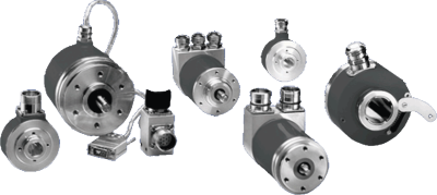
Encoder overspeed switch combinations, redundant encoders, encoders with large hollow shafts, robust encoders for conveyors and steel works.
- Incremental encoders with housing diameter 24 to 145 mm
- Incremental encoders with 4 to 72 mm hollow shaft
- Incremental encoders up to 80.000 increments resolution
- Incremental encoders up to IP 68 / IP 69K (Food industry)
- Incremental encoders with sinus output
- Double- and triple mounting of incremental and absolute encoders for different electrically isolated outputs
- Absolute encoders with housing diameter 36 to 200 mm, single- and multiturn absolute encoders with 10 to 30 mm through hollow shaft
- Absolute encoders up to resolution 17 Bit singleturn und 29 Bit multiturn
- Bus encoders for Profibus, CANopen, CANlift, Interbus, DeviceNet, Ethernet, SSI, parallel, BiSS
- Absolute encoders from 33 mm length (Ø 37 mm)
- Heavy duty incremental and absolute encoders for steel, crane and paper industries
- Linear encoders for length measurement with glass scale or long length metal tape up to 30.040 mm
- Incremental and absolute linear encoders
- Angular encoders up to resolution 1.800.000 increments (interpolated)
MELYE encoder catalogue 2023
MEYLE Incremental Encoder
Comprehensive range of incremental encoders as solid shafts and hollow shaft versions.
MEYLE Absolute encoder
Comprehensive range of absolute encoders as solid shafts and hollow shaft versions.
MEYLE Linear Incremental Encoder
Linear encoders measure the position of linear axis and are suitable for positioning accuracy on machines. The scales are protected against chip, dust and cooling water and are designed for use on various machine tools and installations. Please find a wide range of linear encoders.
MEYLE Overspeed switch
Comprehensive range of overspeed switches.
MEYLE Draw wire encoder
Here you will find our draw wire encoder Ref. CD50, Ref. CD60 and Ref. CD80
Systems
The use of a network of sensor-actuator bus systems has essential advantages:
• Reduced expenditure concerning connection: All members are linked by one cable.
• Reduced expenditure concerning connection: All members are linked by one cable.
Interface
BiSS is a fully-digital and bi-directional sensor interface. lt defines communication between one master and several slaves (sensors) in industrial control systems.
Code TYPES
To transfer the position data to a controller, different interfaces are available.
Applications
Stop dog positioning
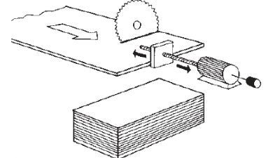
Workpiece lengthmeasurement system with opto electric and encoder
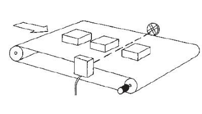
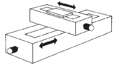
Crosstable positioning
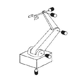
Roboter axis control
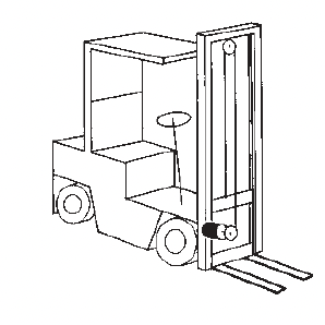
Fork hight measuring at fork trucks
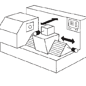
Positioning at CNC-tooling-machines
Valve position control
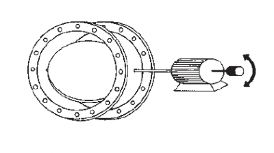
Length dimension with measuring wheel
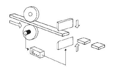
Lengthmeasuring of textile or paper rolls
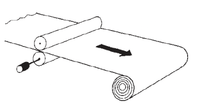
Tensile stress control
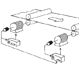
Control of transport vehicles
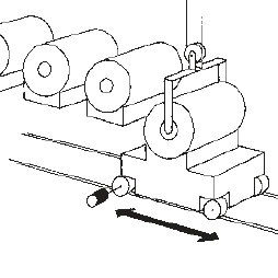
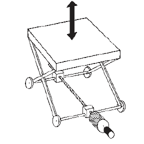
Adjustment of lift platforms
GENERAL/OVERVIEW
General
Conformity:
All Meyle encoders fully comply with the CE-regulations and are intensively tested in our EMC laboratories.
They conform to CE requirements according to EN 50082-2, EN 50081-2 and EN 55011 class B.
High quality of signals:
All encoders from Meyle, are equipped with ageing and temperature compensation to ensure a long term and stable signal also after many years of operation.
Ageing compensation:
The direction of rotation may no longer be detected. Properly by the control,aspecial electronic circuit, which is built in the specific ASIC prevents this effect.
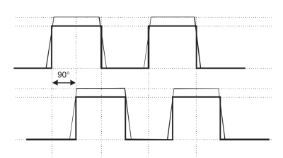
Each LED source will inevitably lose it’s power over a period of time. As a result, the output signal degrades. The phase shift between channel A and B of 90° becomes less and less.
Signals of a new encoder or encoders with ageing compensation:
Signals of an older encoder without ageing compensation:
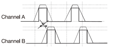
Benefit: The ageing compensation circuit ensures the same signal, even after many years of operating time. The down time of machines will be reduced dramatically and the reliability is increased.
Temperature compensation:
This specialised circuit ensures that the qual-ity of the signal will stay on the same high level over the whole working temperature range.
Benefit
The positioning accuracy of a machine will not be affected by temperature changes.
Environmental conditions:
A significant influence on the lifetime of the encoder is set by the environment in which the encoder is operating, e.g.:
• The ambient temperature
• The expected shaft load
• The possible grade of dust/dirt and humidity/liquids
• The ambient temperature
• The expected shaft load
• The possible grade of dust/dirt and humidity/liquids
The support design and the use of high quality components makes our encoders suitable for applications in rough conditions.
Many references such as from Bosch, Siemens, Bombardier and other customers proof these high requirements.
Many references such as from Bosch, Siemens, Bombardier and other customers proof these high requirements.
Temperature:
Definition according to DIN standards 32 878
Working temperature:
Is defined as the environmental temperature, in which the encoder will produce the signals defined in the data sheets.
Operating temperature:
Is defined as the environmental temperature which the encoder can withstand without getting damaged.
Dirt/dust and humidity/water:
The second digit defines the resistance against water. The higher the number, the higher the water pressure can be. Our encoders have a protection up to IP 67. These two tables summarise the most used IP ratings:
The IP classification according to EN 60529 describes how the encoder is protected against particles and water. lt is described as an abbreviation "IP" followed by two numbers. The first digit defines the size of the particles. The higher the number the smaller the particles.
Protection against particles (first digit):
| 0 not protectet |
|---|
| 1 protected against particles 50 mm and larger |
| 2 protected against particles 12,5 mm and larger |
| 3 protected against particles 2,5 mm and larger |
| 4 protected against particles 1,0 mm and larger |
| 5 protected against dust |
| 6 dust proof |
Protection against water (second digit)
| 0 not protectet |
|---|
| 1 protected against falling drops of water up to 15° from vertical |
| 2 protected against falling drops of water up to 15° from vertical |
| 3 protected against water sprayed up to 60° from vertical |
| 4 protected against water sprayed from all directions, limited ingress permitted |
| 5 protected against low pressure jets from all directions, limited ingress permitted |
| 6 protected against strong jets of water, e.g. for use an ship decks, limited ingress permitted |
| 7 protection against the affects of immersion between 15 cm and 1 m |
| 8 protected against lang periods of immersion under pressure |
Designation of colours to DIN standard 757
| abbreviation | colour |
|---|---|
| BK | black |
| BN | brown |
| RD | red |
| OG | orange |
| YE | yellow |
| GN | green |
| BU | blue |
| abbreviation | colour |
|---|---|
| VT | violet |
| GY | grey |
| WH | white |
| PK | pink |
| GD | gold |
| TQ | turquoise |
| SR | silver |
Shaft Load:
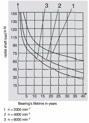
Due to misalignment and other mechanical influences from outside, the shaft of the encoder is exposed to a number of different loads. This has a direct impact on the lifetime of the ball bearings and also on the electrical signal itself. lf there is an over- load there will be an early wear and in the worst case it will lead to a failure of the unit and to a destruction of the optical system inside. For shaft encoders the maximal radial and axial load should not be exceeded. lt is highly recommended to use a coupling between the encoder shaft and the drive shaft, see also the accessories and the mounting suggestions.
In the technical data sheets of the encoders, typical values for the radial and axial load at the shaft end are listed. This is based on the lifetime of the ball bearing, the speed, the mechanical load and the temperature. To easily find the lifetime for the specific application the following diagrams can be used. All of the diagrams are based on the following parameters:
• 60° C environmental temperature
• The axial load is always half the load compared to the radial load
• 60° C environmental temperature
• The axial load is always half the load compared to the radial load
Type series 58 mm diameter
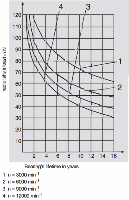
Type series 90 mm diameter
