MEYLE lncremental encoder
Assembly and function:
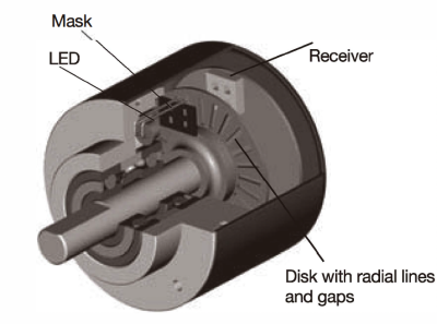
Meyle encoders operate on an electro-optical scanning principle. A disk with a radial grating of lines and gaps rotates between a light source (mostly a LED) and a receiver which produces a sine wave signal proportional to the light received.
Processing of the signals:
The sine wave signals are processed further in an electronic circuitry, usually a specific ASIC. This is necessary because most controllers controls (like e.g. counters) require digital signals with a certain voltage
level. For that the signals are pre-processed in the encoder. The pre-processed signals are transmitted by the output circuit depending on the application.
Selecting an Incremental encoder
When selecting the encoder, following parameters should be considered in addition to the topic mentioned on page 8-10.
Encoders with one output channel
Number of channels:
Encoders with one output channel are used speed control or length measuring. where no direction sensing is needed, e.g.
speed control or length measuring.
Encoders with two output channels
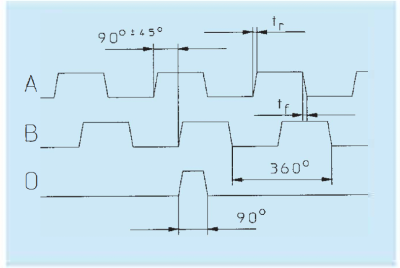
Applications, where the direction of a rotation should be sensed, e.g. positioning, require encoders with two channels A and B being shitted 90° out of phase. By detecting the phase shitt, the direction can be located.
Encoders with three output channels
In addition to the two channels A and B there is a zero signal available, that appears once per turn. This can be used e.g. as a reference signal during the first revolution atter power up.
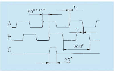
tr = rise time
tf = fall time
tf = fall time
- Shatt turning clockwise, top-view of shatt
- lnverted signals available
- 0-pulse is linked to AND with channel A and B
Multiplication of pulses:
An encoder with physically 5000 pulses per revolution can generate 20000 pulses per revolution using this technique
The resolution of a two channel encoder can be multiplied by two or four using a special edge detecting.
lnverted signals:
signals. These signals are always available with output circuits of the RS 422 type and sine wave outputs. Meyle also offers them for push-pull outputs.
When used in environments, with a lot of electrical noise and/or if very lang cable distances are required, we recommend to use encoders with inverted (complementary)
Resolution:
Example: An encoder is equipped with a measuring wheel. Every revolution corresponds to a distance of 200 mm (circumference). The accuracy should be 0, 1 mm. What is the required resolution (ppr)?
Given: Circumference of the measuring
wheel: U = 200 [mm]
Accuracy of the system: G = 0, 1 [mm]
Wanted: Resolution of the encoder: A = ? [pulses/resolution]
resolution = Circumference !!_
Accuracy G
The required resolution would be 2000 ppr (pulses per revolution).
wheel: U = 200 [mm]
Accuracy of the system: G = 0, 1 [mm]
Wanted: Resolution of the encoder: A = ? [pulses/resolution]
resolution = Circumference !!_
Accuracy G
The required resolution would be 2000 ppr (pulses per revolution).
Pulse frequency:
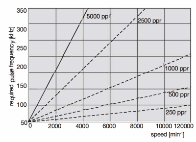
The required pulse frequency can be calculated. This is based on the number of pulses per turn (ppr) and the speed (rpm). The max. pulse frequency is listed for each encoder. Usually it is 300 kHz. Meyle also offers high resolution encoders with a pulse frequency of up to 800 kHz.
Example
of how to calculate the required pulse frequency fmax:
Given: Speed n= 3000 min-1
Resolution of the encoder R = 1000 ppr
Given: Speed n= 3000 min-1
Resolution of the encoder R = 1000 ppr
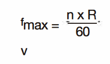
The required pulse frequency is 50 kHz. Now you can compare this result with the data of the encoder you would like to choose.
This diagram can be used for the most common resolutions as a quick guide:
Outputs and Voltage supplies (overwiew):
Meyle offers a wide range of possible outputs and voltage supplies for any application.
| Output | lnverted signals | Sensor output |
|---|---|---|
| RS 422 | Yes | 5V DC |
| RS 422 | Yes | 10 ... 30 V DC or 5 ... 30 V DC |
| Push Pull output | No | 10 ... 30 V DC or 5 ... 30 V DC |
| Push Pull outpu | Yes | 10 ... 30 V DC or 5 ... 30 V DC |
| Sine wave voltage output | Yes | 5V DC |
| Sine wave voltage output | Yes | 10 ... 30VDC |
lf the encoder is used in an environment with strong electrical noise and lang cables we highly recommend the use of inverted signals.
Sensor outputs:
on the sensor output line is almost zero. Due to this it is possible to detect the actual supply voltage of the encoder (e.g. 4,2 V instead of 5 V). Based on this information the controller will increase the voltage supply to e.g. 5,8 V.
The sensor outputs are used if the distance from the encoder to the control unit is very lang and the voltage supply at the encoder could drop due to this lang distance. The input impedance of the sensor inputs (Controller) is very high, and the voltage drop
Digital outputs:
The sine wave signal from the optical system is first digitised to have square wave signals available.
- Shaft turning clockwise, top view of shaft
- Inverted signals are available
- 0-pulse is linked to AND with channel A and B
- The corresponding unit / controller the encoder will be connected to
• The distance from the encoder to the receiver unit
• The sensitivity against electrical noise or other interferences.
Push-pull:
Push-pull outputs are suitable for count interface cards, electronic counters or PLC inputs.
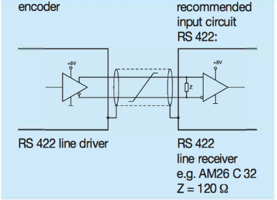
Output circuit and recommended input circuit RS 422:
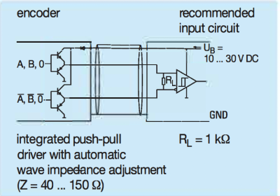
Output circuit and recommended input circuit push-pull with inverted signals:
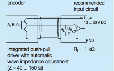
Output circuit and recommended input circuit push-pull without inverted signals:
Sine wave outputs:
The sine wave signals are available as voltage signals. They can be further processed and can be multiplied by a factor of usually 10, 20, 50, 100, 400, 500, 1000 res. binary factors (512, 1024). Due to the interpolation of the two signals, which are 90° out of phase, a very high resolution can be achieved. This makes these kind of signals specially useful for applications where very high resolutions are required. Further they are very suitable for digital drives with a very slow and precise movement, e.g. for grinding machines or lifts and elevators.
• Shaft turning clockwise, top view of shaft
• 0-pulse is generated once per turn
Output circuit and recommended input circuit for sine wave voltage signals:
Gable length:
Depending on the output circuit and the electrical noise the following cable lengths are recommended:
| Output Circuit | max. cable length | Encoder connected to e.g. |
|---|---|---|
| Push-pull without inverted signals | 100 m | counter/PLC |
| Push-pull with inverted signals | 250 m | PLC/IPC1) |
| RS 422 with inverted signals | up to 1000 m (> 50 m depending on frequency) | PLC/IPC1) |
| Voltage sinus with inverted signals | 50m | PLC/IPC1) |
| 1)1PC = industrial PC |
Annotations:
- Depending on the application the recommended cable length can be shorter, especially in areas with strong electrical noise.
- Always use shielded cables
- The core diameter of the signal cores should be 0 0, 14 mm2
- The core diameter of the voltage supply cores should be large enough depending on the cable length, that the voltage supply of the encoder is high enough and the signals do not go below the minimum levels!


